Spinning rocket
Gas carried by the rocket is heated by a chemical reaction and expelled to provide thrust. At least 1 trillion (1012) U.S. dollars have been spent over nine centuries on rocket research. Unfortunately, rocket launchers remain expensive and prone to failure due to temperature extremes, enormous heat flux in the throat of the thrust chamber, severe vibration, low reliability of high-performance turbopumps, and the use of corrosive and flammable chemicals. Hot oxygen corrodes most structural materials in a matter of seconds. Refractory materials survive a few minutes. It takes extraordinary amount of research and experimentation to prevent meltdown and explosion of a newly designed rocket launcher. Most rocket launchers are expendable (disposable). The Space Shuttle is salvageable. Reusable rocket launchers do not exist. Cargo transported by rockets is called payload. The accent is on pay because it costs about $10,000 to launch 1 kilogram of cargo to a low Earth orbit. The ratio of cargo mass to the total mass of the rocket including its cargo and propellant is called payload fraction. Its value ranges from 6 percent for liquid propellant rockets to 0.2 percent for solid propellant rockets. The minimum mass of a chemical rocket launcher (for 1-ton cargo) is about 20 tons.
If we ignore gravity and aerodynamic drag, the final velocity of a rocket equals:
The total_mass includes everything: rocket engine, structural parts, propellant, and cargo. The dry_cargo_mass is the mass of the rocket engine, structural parts and cargo. The ratio of total_mass to dry_cargo_mass is called mass ratio (MR). According to the above formula, which is known as the rocket equation, a high velocity of exhaust gas is needed to launch massive cargo. Dividing the rocket launcher into several stages also helps, but it makes the staged launcher more complex than the single stage launcher.
Specific impulse describes propulsive efficiency of
all contraptions which generate thrust by consuming fuel or
rocket propellant. The specific impulse is defined as impulse
produced by one kilogram of fuel or propellant. Metric units
of the specific impulse are Ns/kg or m/s (meter per second).
The specific impulse of a rocket is the same as its
exhaust gas velocity, but the specific impulse of an
air breathing engine is one order
of magnitude greater. Most rocketeers express the specific
impulse in seconds and calculate it by dividing the exhaust
gas velocity by 9.8. All values of specific impulse given
in this publication pertain to rockets immersed in a vacuum.
The maximum velocity of the exhaust gas is
about twice its
speed of sound:
Umax = A0(2/(G-1))0.5
The high exhaust gas velocity calls for high pressure in the
combustion chamber, high expansion ratio, and a hot gas having
low molecular mass. The ratio of the exhaust nozzle exit area
to the throat area is called the expansion ratio or
the nozzle area ratio. To maximize the specific impulse,
some researchers attempt to build rockets propelled by
pure hydrogen heated either by
electric current, or a
laser, or
microwaves, or a
nuclear reactor.
Failure of the Space Shuttle and other expensive rockets to reduce the cost of space transportation has persuaded NASA and private rocketeers to experiment with simple rocket launchers. They are often called 'big dumb rockets' or 'big dumb boosters.'
A rocket launcher must be reusable in order to be economical. This means that it must have liquid propellant engine with either regenerative cooling (plumbing circulating cold propellant), or radiative cooling, it must withstand high stress during atmospheric reentry, and it cannot use expensive, ablative shield protecting it from the heat during reentry. The high cost of the ablative reentry shield may be reduced or eliminated by:
There are eight types of chemical rockets:
Small rocket engines have many advantages over big
engines. Engine development costs increase exponentially with
thrust.
Combustion instability is a common problem in prototypes of
big, high-pressure, liquid propellant engines. The instability is
caused by turbulence, which is determined by the Reynolds number.
Gas viscosity is primarily a function of temperature. The impact of pressure is minor and the viscosity correction for pressure is less than 10% for up to 3.5 MPa. This means that the Reynolds number is proportional to the chamber's diameter and to the gas density, which is proportional to its pressure. The turbulence in small, low pressure engines is too small to disturb the protective layer of cool gas adjacent to the chamber's wall. This means that these engines are inherently more durable than the big, high-pressure engines. The high Reynolds number also damages large turbopumps because it is the main cause of cavitation and vibration. The most extreme engine instability results in pulsed flow of the propellant into the chamber. To prevent this extreme instability, the propellant must be pumped into the large engines at much higher pressure than the combustion chamber pressure. Small, pressure-fed engines do not need high tank pressure to prevent the extreme instability, so their tanks are relatively light-weight. Another reason for the superior thrust-to-weight ratio of small rocket engines is the Cube-Square Law which states that as scale is reduced, properties which are a function of volume (mass) will decrease faster than those which are a function of area (thrust and strength).
The Cube-Square Law also applies to the entire rocket launcher. Structural stress during atmospheric reentry is so severe that it would destroy any rocket bigger than the Space Shuttle. The Space Shuttle is a compromise; it jettisons its external fuel tank to reduce its size and structural stress. Big, single-stage rocket launchers cannot return to the Earth, so they are neither reusable nor economical.
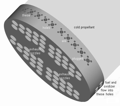
Centimeter-size engines have as many advantages as disadvantages when compared with meter-size engines. The tiny engines weigh little even if walls of their combustion chambers are thick compared with their size. The thick walls conduct heat well, so they can be cooled by thermal contact with liquid oxygen tank instead of the expensive regenerative cooling. Failure of a few engines out of a few thousand is not a catastrophe, so poor quality engines can be used and reused many times. Tiny engines have tiny combustion chambers. A crude rule of thumb says that specific length of the combustion chamber must be at least 60 cm to ensure thorough mixing of fuel and oxidizer. The specific length L* is defined as the chamber volume divided by the throat area. If the specific length is less than 60 cm, the fuel and oxidizer must be very volatile and the injector holes must have diameter much smaller than one millimeter. Hydrocarbon fuel is not desirable because it may polymerize at high temperature and plug-up tiny fuel lines. Although miniature piston pumps can provide enough pressure, they are not nearly as efficient as the large turbopumps.
Standard injector holes have cylindrical shape and diameter of about one millimeter. Smaller holes are desirable because they reduce volume of the combustion chamber and combustion instability. The best tool for making small injector holes is a powerful electron beam. The beam can make one hole having diameter of 50 µm in one millisecond. Other methods are at least one order of magnitude slower. Lasers are not suitable for making holes in aluminum and copper because these metals reflect the laser beams. Carbon dioxide lasers are reliable, inexpensive, and suitable for making holes having diameter larger than 50 µm. Excimer lasers can make holes as small as 5 µm, but they are expensive and less durable. The electron and laser beams can make tapered holes which improve the rate of propellant flow. Rounded hole inlets also improve the rate of propellant flow because they prevent cavitation. Mechanical drilling and EDM (electrical discharge machining) cannot make holes smaller than about 100 µm, and cannot make tapered holes.
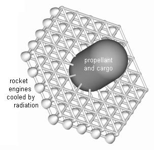
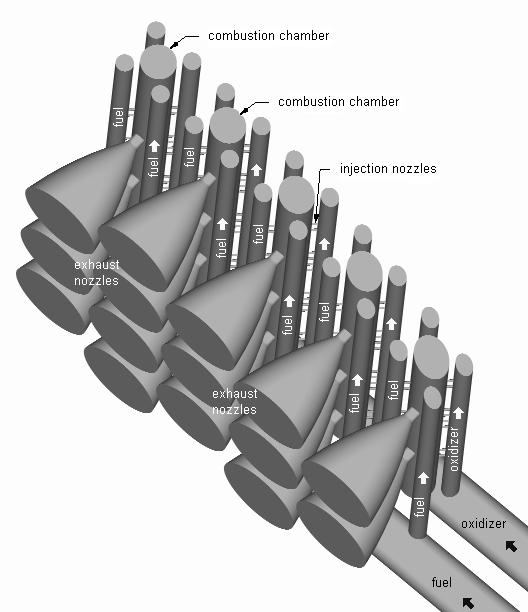
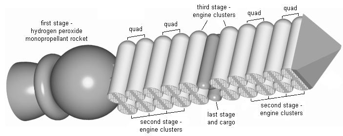
Engine cluster is a multitude of decimeter-size engines carved in a monolithic slab of aluminum alloy. The slab is also the bottom wall of the liquid propellant tank and a heat sink during atmospheric reentry. The tank is integral part of the engine cluster. It holds liquefied oxygen or liquefied methane which are self pressurizing propellants. When pressure in the methane tank is too low, a pressure switch turns on a fan which churns the liquid methane inside the tank. The liquid absorbs heat permeating from the engine and vaporizes. Vapor pressure forces the liquid into a spiral channel carved in the slab. The liquid flowing in the channel cools the engine before entering the combustion chamber. Combustion chamber pressure is only 1 MPa because higher pressure would generate excessive heat flux in these poorly cooled engines. Expansion ratio of the engine cluster is about 10, its specific impulse is about 3 km/s, and its mass ratio is about 15 -- two times higher than the mass ratio of the big dumb boosters made of the same materials. Rocket cluster is a rocket launcher made of engine clusters stacked on top of a reusable hydrogen peroxide monopropellant rocket.
The conventional engines are large, complex, hand-crafted, and made of pipes welded together. They cost about $7000/kg. The engine cluster is much cheaper because it can be made by a milling robot which carves the engine from a monolithic slab of aluminum alloy. (Similar method was used to make thrust chamber of the Agena rocket engine -- coolant passages were drilled in a monolithic slab of aluminum alloy.) The small size of the engines and low pressure of the exhaust gas reduces turbulence which is the main cause of premature failure of liquid rocket engines. The best material for the monolithic slab is aluminum 6061-T91 alloy. This alloy is machinable, weldable, and has thermal conductivity of 170 W/mK. Titanium alloys have greater specific strength (strength-to-weight ratio), but their thermal conductivity is too low for regeneratively cooled engines. The best drilling coolant for aluminum alloys is kerosene. Soft aluminum gums up ordinary drill bit flutes, so special drill bit is preferable. Aluminum alloy called Weldalite 049-T8 is the best material for the cryogenic tanks of the second stage because it is strong, light-weight, weldable, and has the same coefficient of thermal expansion as the aluminum engine. Its yield tensile strength is 690 MPa.
The third stage of the rocket cluster is made of the aluminum engines and titanium tanks. Joining the aluminum engine with the titanium tank is difficult, but the titanium tank is better suited for the high temperature of the atmospheric reentry. A gasket made of Teflon or Kapton is wrapped around the aluminum engine before the engine and the tank are immersed in liquid neon. The engine is placed inside the tank and both parts are warmed up. A tight bond between the two parts forms as a result of different coefficient of thermal expansion of aluminum and titanium.
Thrust produced by a pressure-fed rocket engine is so low that a long, pressure-fed rocket cannot lift itself off the ground. A cluster of short, pressure-fed rockets seems impracticable because it would generate too much aerodynamic drag during flight through the atmosphere. To reduce the drag, short engine clusters are stacked sideways and lifted to the altitude of about 30 kilometers by the reusable hydrogen peroxide monopropellant rocket. Each engine cluster has diameter of about one meter and length of about five meters -- one order of magnitude shorter than the length of conventional rocket launchers. The short rockets are relatively more sturdy than long ones. The engine clusters are strong enough to survive reentry, splashdown, and handling on a bobbing ship. During the reentry the engines are on the hot, fore side of the engine cluster. When the reentry begins the engines are used as heat sinks. When they reach maximum safe temperature, they are cooled by residual vapor flowing through them.
Although the hydrogen peroxide monopropellant rocket burns
lots of expensive propellant, it is the best choice in the short
term because its design is cheap and simple. In the long term
the rocket should be replaced with a more efficient contraption:
either a steamjet engine, or
a helicopter.
The helicopter used as the first stage of the rocket launcher
(helicopter-rocket relay) is more reusable and slower than other
first stage alternatives. It has two sets of propellers: small
propellers generate thrust during flight through the troposphere,
while big propellers generate thrust during flight through the
stratosphere. The slow motion of the helicopter is perfectly
suited for large, low density cargo, for example large telescope
or large greenhouse. The launcher scales down very well because
it is reusable and because Its atmospheric drag is negligible.
The negligible atmospheric drag makes it possible to use very
large exhaust nozzles which improve the expansion ratio and
specific impulse. Last, but not least, the shape of the exhaust
nozzles can be optimized for flight in the vacuum.
The helicopter needs special engines that can operate at
the altitude of 30 kilometers. There are three such engines:
Electric motors powered by batteries are the best choice
because they are cheap, reliable, safe, and easy to use. The
motors and the batteries need a cooling system when they
operate at high altitude.
Magnesium hydride battery with Ni catalyst has the highest
energy density but it is not yet mature technology. Li-ion
batteries have energy density of only 534 kJ/kg, but they are
very reliable and reusable. (They provide auxiliary power for
my laptop computer.) The Li-ion batteries can be used as the
power source despite their low energy density if used up
batteries are discarded during the flight. It takes about 300
watts of helicopter power to lift 1 kg of weight. At the
beginning of the flight the total weight of the batteries is
about one half of the launcher weight. During 15 minutes of
vertical flight the helicopter reaches its maximum altitude of
30 km, drops off nearly all its batteries on parachutes, and
finally drops off the launcher. When the helicopter descends,
most of its propellers (rotors) are used as wind turbines which
provide power for the remaining propellers and charge the
remaining batteries. The remaining batteries are used up during
landing.
If the cost and energy density of the rechargeable batteries
do not improve in the future, the best source of power for
the motors in the long term may be microwaves. Leik N. Myrabo
pioneered the idea of microwave powered helicopters.
Aluminum wires linking the motors with a high voltage generator
standing on the ground would be expensive and difficult to use.
Roton is a liquid propellant rocket which substitutes
centrifugal force for the expensive turbopumps. Depending on design,
either the entire rocket or its part rotates about vertical axis.
It looks like the Hero engine, except that
it has helicopter-like blades which provide lift during flight
through the atmosphere. The centrifugal force is too weak to
pressurize low density propellants, but it is sufficient to
pressurize the hydrogen peroxide monopropellant.
Another unique design is the hydrazine catalytic decomposition
rocket engine. It uses a single chemical: liquid hydrazine (N2H4).
Hydrazine is very toxic and unstable at high temperatures. In the
presence of a catalyst, hydrazine decomposes into nitrogen, ammonia,
and hydrogen. The specific impulse in vacuum is 2.3 km/s. This
reliable rocket engine controls the attitude of communications
satellites and the roll of the upper stages of rocket launchers.
A
reusable hydrogen peroxide monopropellant rocket has
similar design. 100% hydrogen peroxide monopropellant has density
of 1450 kg/m^3, specific impulse at sea level of 1.6 km/s and
exhaust gas temperature of 1285 K. 75% hydrogen peroxide
monopropellant has density of 1330 kg/m^3, specific impulse at
sea level of 1.15 km/s and exhaust gas temperature of 630 K.
Mixing ingredients of the grain is dangerous because the mixing
tool may scrape a solid surface and thus make a spark which ignites
the grain. The liquid grain is cast into the rocket case and allowed
to harden and cure. Extreme care must be taken during casting to
ensure good bonding of the grain to the case wall and to avoid the
formation of cracks and voids. The larger the rocket, the more
susceptible it is to the formation of the cracks. A fast burning
solid propellant may explode while it burns.
Bruce Dunn post on sci.space.tech.

Hexagonal rocket
cluster launcher
The hexagonal launcher is
more compatible with the helicopter first stage because
it is structurally stronger.
- Hydrogen peroxide monopropellant turbine.
- Steamjet engine.
- Electric motors.
Roton profile

Liquid rocket in tube profile
Solid propellant rocket profile
Candle rocket profile
Solid rocket in tube profile
Hybrid rocket profile
Environmental Aeroscience Corporation.
AeroTech RMS/Hybrid Reloadable Motor.
SpaceDev Hybrid Rocket Program.
Steam rockets cannot be used as rocket launchers because their specific impulse is too low and their dry weight is too high.
Rapid manufacturing (also known as direct manufacturing) is an additive fabrication technology that makes complex plastic or metal parts automatically from data held in STL files. (STL files are made by CAD programs.) Metal parts produced by a sintering process are cheap, but they are porous and have poor corrosion resistance. Two technologies produce metal parts that are not porous and therefore resistant to corrosion and suitable for rocket engines. These technologies utilize laser or electron beam to melt metal powder feedstock.
The laser method is used by Optomec LENS-850 system. The system is slow (fabrication speed is about two cubic millimeters per second) and expensive. The maximum part size is 46cm x 46cm x 107cm.
Arcam EBM S12 electron beam system is faster than Optomec (about 17 cubic millimeters per second). The maximum part size is 20cm x 20cm x 18cm.
The best materials for regenerative rocket engines (aluminum and copper) reflect the laser beam (albedo up to 98%) rather than absorb it. The high albedo and poor energy efficiency of lasers (typically less than 10% of electric energy is converted to laser beam energy) strongly favor the Arcam electron beam system. A powerful electron beam is easier to generate and deflect than a powerful laser beam. Laser beams are deflected by moving parts which cannot match the scanning speed of the electron beam and require too much maintenance.
The best source of information about rapid manufacturing is the annual Wohlers Report ($390).
K. K. Kuo and M. Sommerfield, (editors) Fundamentals of Solid-Propellant Combustion, AIAA, 1984.
Gregg Easterbrook, "Big Dumb Rockets," Newsweek, August 17, 1987.
Dieter K. Huzel and David H. Huang, Modern Engineering for Design of Liquid-Propellant Rocket Engines, AIAA, 1992, ISBN 1-56347-013-6.
Alain Davenas (editor) Solid Rocket Propulsion Technology, Pergamon Press, January 1993, ISBN 0080409997.
A. H. Epstein, et. al. "Micro-Heat Engines, Gas Turbines, and Rocket Engines: the MIT Microengine Project," AIAA 97-1773.
M.N. Ross, J.R. Benbrook, W.R. Sheldon, P.F. Zittel, and D.L. McKenzie, "Observation of Stratospheric Ozone Depletion in Rocket Exhaust Plumes," Nature, Vol. 390, 1997a, pp. 62-64.
Oscar Biblarz, George Paul Sutton, Rocket Propulsion Elements, 7th edition, Wiley-Interscience, December 2000.
Alan Leo, "Pocket Rockets Pack a Punch," Technology Review, May 18, 2001.
TDK (liquid rocket engine performance program).
JANNAF (Joint Army-Navy-NASA-Air Force) Handbooks and Manuals.
CPIA (Chemical Propulsion Information Agency).
Digital Micro-Propulsion research at California Institute of Technology.
Gregg Easterbrook, "Long Shot," The Atlantic Monthly, May 2003.